Physics Overview
PowerZooJax models the integrated electricity system as one grid spanning generation, transmission, distribution, end-use DER, and a data center microgrid. This page gives a high-level spatial and functional overview of these domains and how they connect.
System Architecture
PowerZooJax first connects the physical task suite to the JAX training path:
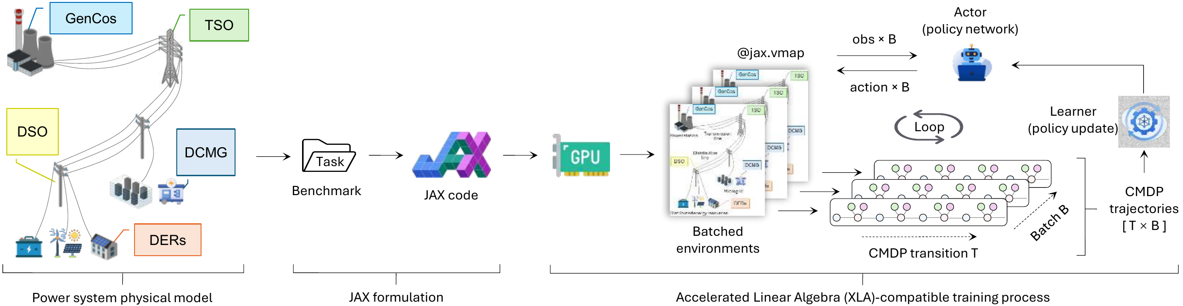
Figure 1. Execution paradigm of PowerZooJax: five power-system CMDP tasks are expressed as JAX code, batched on GPU with jax.vmap, and consumed by actor-learner training loops as [T × B] trajectories.
Figure 1 should be read left to right. The labeled physical tasks (GenCos, TSO, DSO, DERs, and DCMG) become a benchmark task family, then fixed-shape JAX code, then GPU-resident batched environments. The right side shows the training loop: batched observations go to the actor, batched actions return to the environments, and the learner updates the policy from CMDP trajectories.
The physical power system behind those tasks is one grid spanning five domains, from bulk generation down to a data center microgrid:
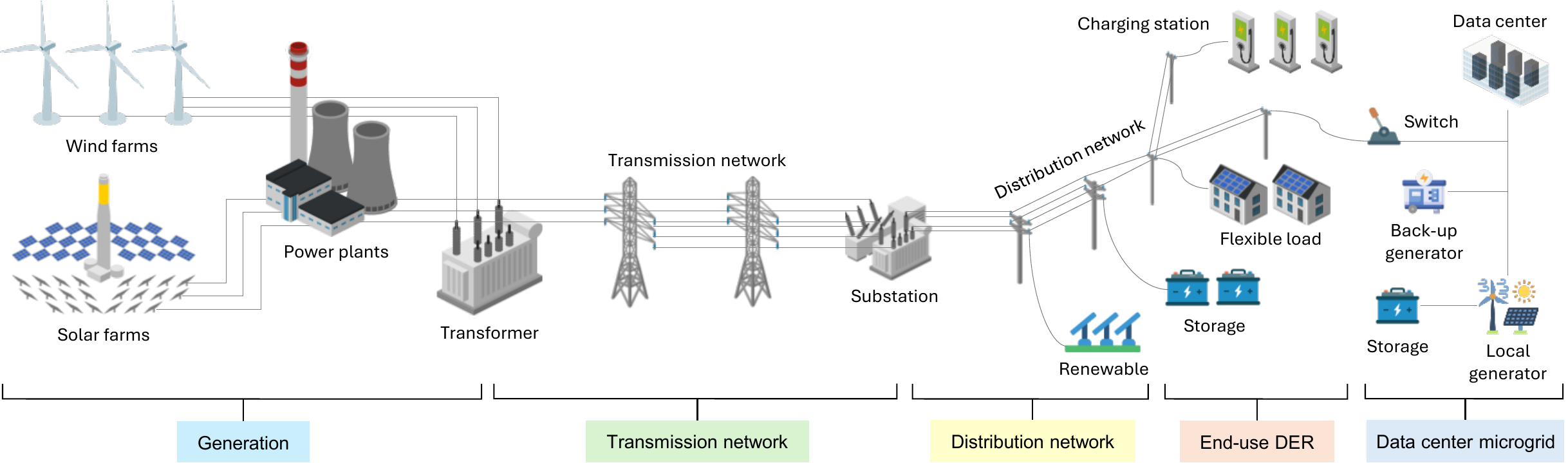
Figure 2. Overview of the modeled power system, spanning generation, transmission, distribution, end-use DER, and a data center microgrid.
How to read Figure 2
Figure 2 is a single-line view of one power system, read left to right as power flows from generation to end use. It groups the grid into the five domains that PowerZooJax turns into benchmark tasks:
- Generation — wind farms, solar farms, and thermal power plants stepped up through a transformer onto the bulk network (GenCos task).
- Transmission network — the meshed high-voltage network and substations that carry bulk power (TSO task).
- Distribution network — radial medium-/low-voltage feeders, including embedded renewable generation (DSO task).
- End-use DER — user-side flexibility behind the meter: EV charging stations, flexible loads, and storage (DERs task).
- Data center microgrid — a local grid coupling a data center with a switch, back-up generator, on-site storage, and local generation, operable grid-connected or islanded (DCMG task).
Power flows left → right, from generation to loads. Each domain maps to one CMDP task; the code-aligned sections below give each model's boundary.
Layer-by-layer model boundaries (code-aligned)
Generation — Supply-side resources
The generation layer represents utility-scale supply that feeds the transmission network:
- Renewables: wind/solar injection following exogenous profiles
- Thermal: controllable plants with ramping, startup, and minimum output costs
- Storage: grid-scale batteries with efficiency and cycling constraints
- Commitment: optional unit commitment decisions in day-ahead style benchmarks
In code, supply-side decisions are realized through transmission environments and factories: - TransGridEnv - UnitCommitmentEnv
Key entry points:
- make_trans_params(...) in powerzoojax.envs.grid.trans
- make_uc_params(...) in powerzoojax.envs.grid.unit_commitment
Transmission system model — Meshed bulk network (TSO)
The transmission system model is TransGridEnv (powerzoojax.envs.grid.trans) plus shared base structs in powerzoojax.envs.grid.base:
- Physics switch:
physics=0(DC PTDF PF),physics=1(AC PF) - Dispatch switch:
solver_mode=0(direct PF),1(DCOPF),2(ACOPF) - Safety/cost outputs: thermal overload, voltage violation, power-balance residual, and resource costs (CMDP-style vector)
- UC extension:
UnitCommitmentEnvextends the grid state with commitment-specific variables while reusing the transmission core
See Transmission Layer.
Distribution system model — Radial feeders (DSO)
The distribution system model is implemented by two environments:
- DistGridEnv (powerzoojax.envs.grid.dist) for balanced radial feeders
- DistGrid3PhaseEnv (powerzoojax.envs.grid.dist_3phase) for unbalanced three-phase feeders
- Radial topology: prepared by
prepare_bfs(...) - Power flow kernels:
bfs_power_flow(...)andbfs_3phase_power_flow(...) - Three-phase safety: explicit VUF tracking (
vuf_max) in the 3-phase env - Factory:
make_dist_params(...)configures solver tolerances, limits, and attached bundles
See Distribution Layer.
End-use DER — Flexible demand and behind-the-meter assets
The end-use DER layer is represented by reusable resource envs/bundles under powerzoojax.envs.resource:
- Flexible demand:
FlexLoadBundle - EV behavior:
VehicleEnv - Storage:
BatteryBundle - PV/renewables:
RenewableBundle - Dispatchable local thermal:
DieselBundle
All bundles follow the same attachable interface (reset/step/observe) and are passed through params.resources=(...) to grid/microgrid envs.
See Resources & Bundles for the reusable asset models used across environments.
Data Center Microgrid system model — Coupled local power + computing
The microgrid system model is DataCenterMicrogridEnv in powerzoojax.envs.microgrid.dc_microgrid, with params built via make_dcmg_params(...).
- Default resource stack:
(BatteryBundle, RenewableBundle, DieselBundle) - Coupled dynamics: battery SOC, diesel output constraints, PV profile-driven injection
- Joint objective: energy cost + data-center workload/thermal terms in one step loop
See Microgrid Layer and DataCenterMicrogridEnv.
What gets coupled across layers (implementation view)
- Energy coupling: generation dispatch and DER injections are assembled into net nodal injections before PF/OPF solves.
- Constraint coupling: line thermal limits, voltage bounds, and (3-phase) VUF limits become explicit cost/safety outputs.
- Resource coupling: attached bundles contribute both injections and per-bundle costs through the shared
resourcesinterface.